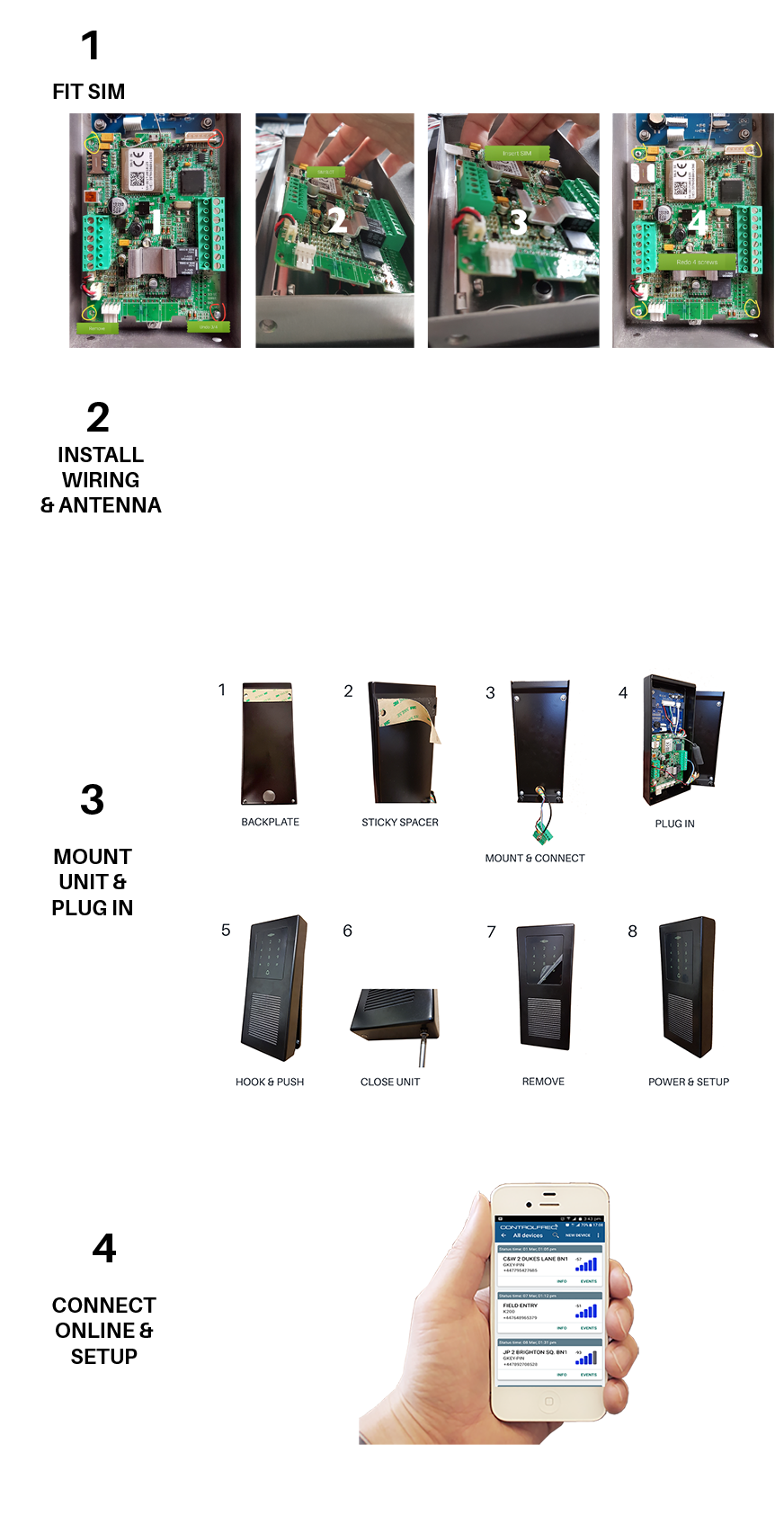
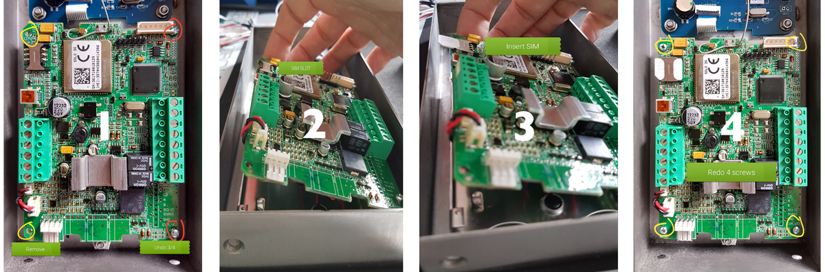
STEP 1. FIT THE SIM CARD
The SIM card is an integral part of the Alpha-3G system. Without a SIM card it will not function.
TIP : Confirm 100% the SIM has Voice, SMS & data active with credit or contract before fitting it to avoid hassle!
As the SIM is in the front panel, it has been designed to make it harder to remove. Leave the two screws on the RHS just in and simply tilt the PCB up to fit the SIM. Close and refit the screws.
Notes:
- Micro SIM required
- Square edges in first (IMPORTANT!)
- Must have data enabled to use Web & App functions
- If calls, SMS & internet work with the SIM in a phone, it will work in Alpha-3G
- Must have credit to call out (test it calls in a phone before using in device)
- Can be on any network in any country (2G or 3G)
2. WIRING
2.1 POWER: Run multi-core alarm cable from the power source location to the intercom position. Note the cable entry position at the bottom of the intercom casing. Make a cut in the rubber grommet and feed wires through it. Do not throw away the rubber grommet. It is to prevent water ingress.
TIP : The terminal blocks on the unit are removable for easier installation
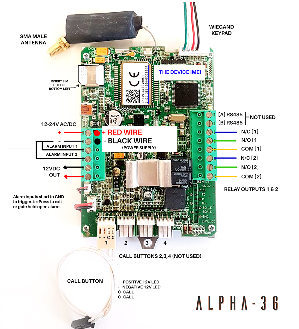
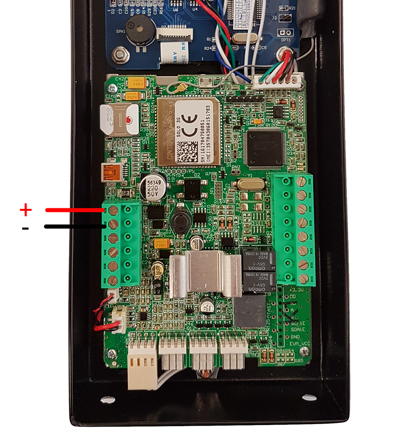
POWER CONNECTIONS
Connect the input power source + and - to the terminals shown below.
2.2 ANTENNA: Run the antenna wiring to a suitable position. Feed the gold plug through the back of the rubber grommet as shown below.
- Feed wires through rubber grommet...

- Connect terminal blocks...

2.3 COMMUNICATION (ONLY REQUIRED FOR SLAVE KEYPAD): If you're using the slave keypad, please note it communicates over Wiegand 26 bit protocol to the main intercom controller so it is recommended to use twisted screened cable to avoid interference issues. The unit will beep at erratic times meaning it's receiving unstable data flow and cause the system to report faulty events to the system log. If this happens, it's the cable...
IMPORTANT : Always use twisted, screened cable for our slave keypads!

2.3 CONNECTIONS (SLAVE KEYPAD ONLY)

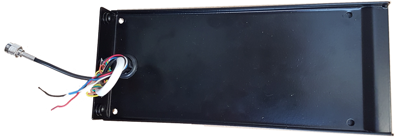
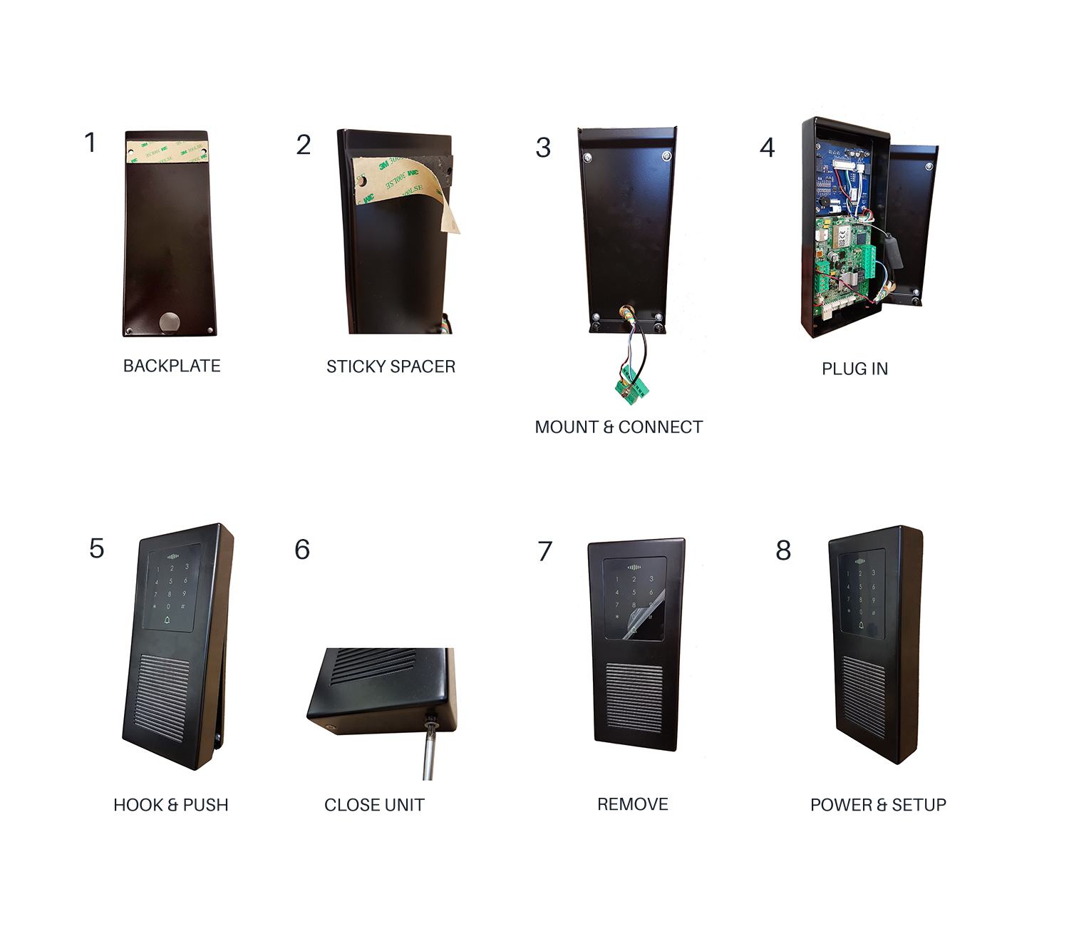
3. MOUNTING
The backplate should be mounted to the wall or post with suitable fixings. The cabling comes through a cut in the rubber grommet.
The front panel slides over from the top and then closes at the bottom. It's tight fit so make sure the top clips in properly before trying to close the unit. Mind your fingers when closing the panel!!
WIRING TIP :Remove the green terminal blocks from the intercom circuit board one at a time. Wire the connections to the terminal blocks paying close attention to the correct wiring terminal positions. Screw on the antenna. Power the system.
TESTING TIP :Before securing the front, plug on the terminals to put power on the device. Let the unit boot up. Clip the front panel loosely over the top to let it hang in place while you test. You will hear 3 quick beeps when it's connected.
5. DOOR / GATE RELEASE
Door release can be controlled in more ways on Alpha-3G that by any other GSM system....
- DTMF: [Press 11 for output 1] [Press 21 for output 2]
- Caller ID: Call the SIM in the intercom from an authorised phone number on the Caller ID list
- PIN code: Enter a valid PIN code then # ie: 1234# (1234 must be set in the PIN access list)
- Prox ID token & Proximity Keyring: Present the keyfob to the keypad area. The last 5 digits (4 if it starts with 0) must be set in the PIN access list) ie: if fob is 55356 (use all 5 digits) if fob is 05356 (use last 4 digits) [ignore the first 3 digits - they relay to facility code which is disabled by default)
- App: Choose 'Direct Controls' from main menu. Label buttons as you choose. Click to control relay outputs.
- SMS: Send ;+ORC1=1; (output 1 ON) ;+ORC2=1; (output 2 ON) ;+ORCx=0; (output 'x' OFF)
CONNECTIONS
5.1 GATES, BARRIERS, SHUTTERS: Connect the COM 1 & N/O 1 to your logic controller COM & OPEN terminals.
IMPORTANT! To avoid potential damage the intercom, do not power electric locks from the intercom power source. For electric strikes & mag locks use a separate power source rated for the lock being powered.
5.2 ELECTRIC STRIKES: Run one of the power feed wires to the strike through COM 1 & N/O 1
5.3. MAG LOCKS: Run one of the power feed wires to the mag lock through COM 1 & N/C 1
5.4. 2ND RELAY OUTPUT: Use the second output for pedestrian open, two locks, door + gate, call disable, etc
TIP : Alpha-3G has 2 internal time-clocks that can be used for holding the gate / door open for preset periods of time throughout the week. You can use output 2 for multiple functions including disabling the call button automatically at preset times.
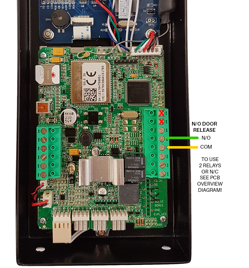
6. PCB OVERVIEW
6.1 COMPLETE OVERVIEW: ALPHA-3G is a serious piece of kit! The main controller is used in all Control Freq GSM intercoms.